Firmware Extraction
This chapter details the performed attempts at extracting the router’s firmware from the S25FL127 flash chip, previously identified on the router’s PCB in the Hardware Analysis chapter.
Extraction was attempted in three ways, to ascertain all the possible ways an attacker could potentially obtain the firmware. These were:
- CH341A programmer and test clips
- TFTP server and U-Boot
- UART flash dump via U-Boot
These attempts are detailed in this order in the sections below.
CH341A programmer and test clips
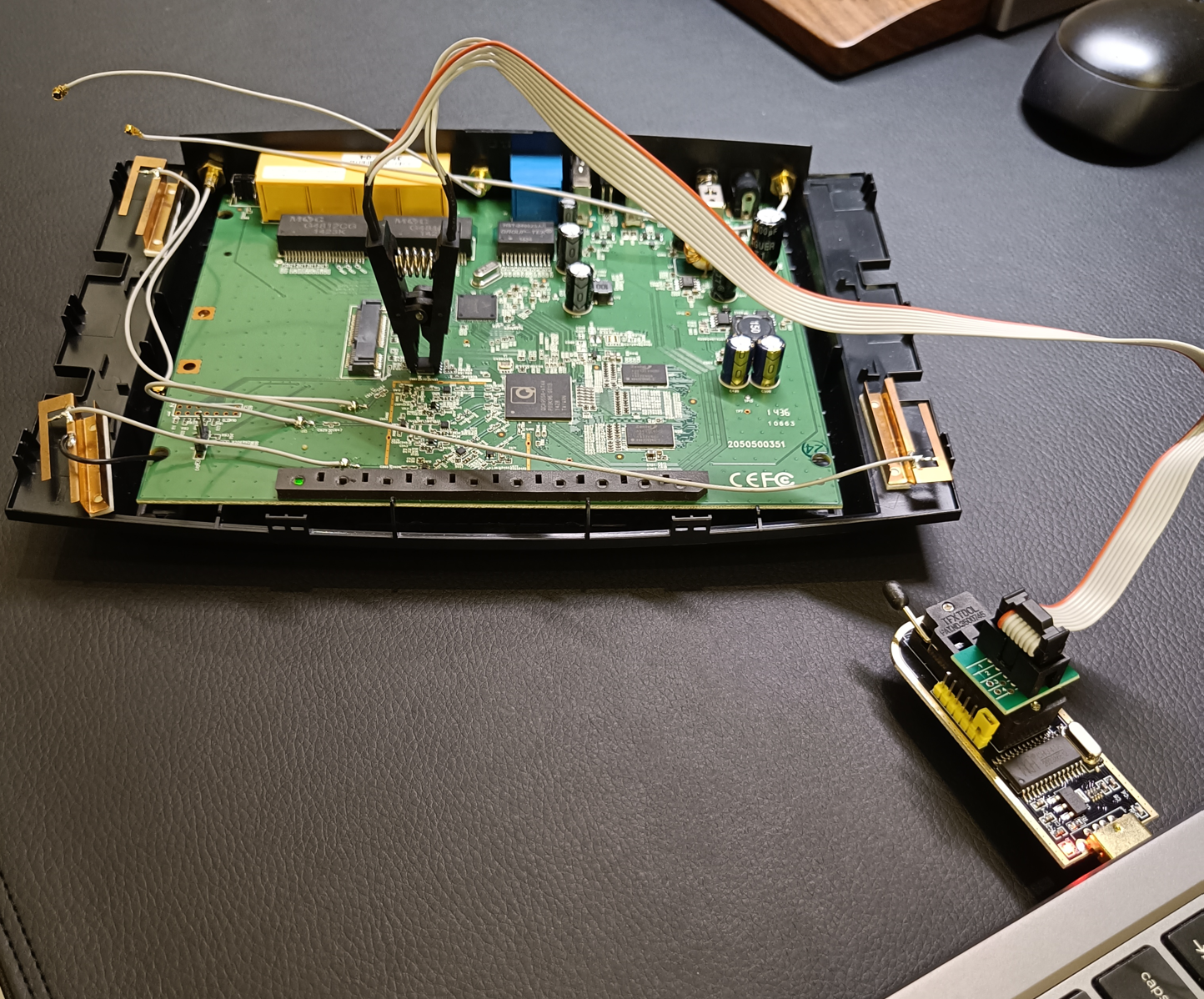
In this attempt at extracting the firmware a SOIC8 test clip was used. This was attached to the flash memory and connected to a CH341A programmer which itself connected to the Kali Linux workstation as can be seen in the image below.
On the workstation side, the flashrom utility was installed and used to attempt a direct read of the SPI flash. For this, the following command was executed.
$ sudo flashrom -p ch341a_spi -r archer_c7_flash.bin
Where the -p ch341a_spi parameter specifies the CH341A SPI interface, and -r instructs flashrom to read the contents of the chip into a file to be named archer_c7_flash.bin. Furthermore, before running the command, the following checklist was followed to verify the setup’s correctness:
- Pin 1 alignment throughout the setup (from the chip to the programmer)
- Ensure robust connection/contact between the clip and the chip
- Ensure router was powered off during extraction
- Flash chip model is supported by
flashrom
However, despite these checks, the extraction attempt failed. Flashrom consistently returned the following error message.
flashrom unknown on Linux 6.8.11-amd64 (x86_64)
flashrom is free software, get the source code at https://flashrom.org

Using clock_gettime for delay loops (clk_id: 1, resolution: 1ns).
No EEPROM/flash device found.
Note: flashrom can never write if the flash chip isn't found automatically.
Since it was suspected that the problem lied in the test clip connection with the flash chip, a new attempt using individual test clips was tried, as seen in the images below.
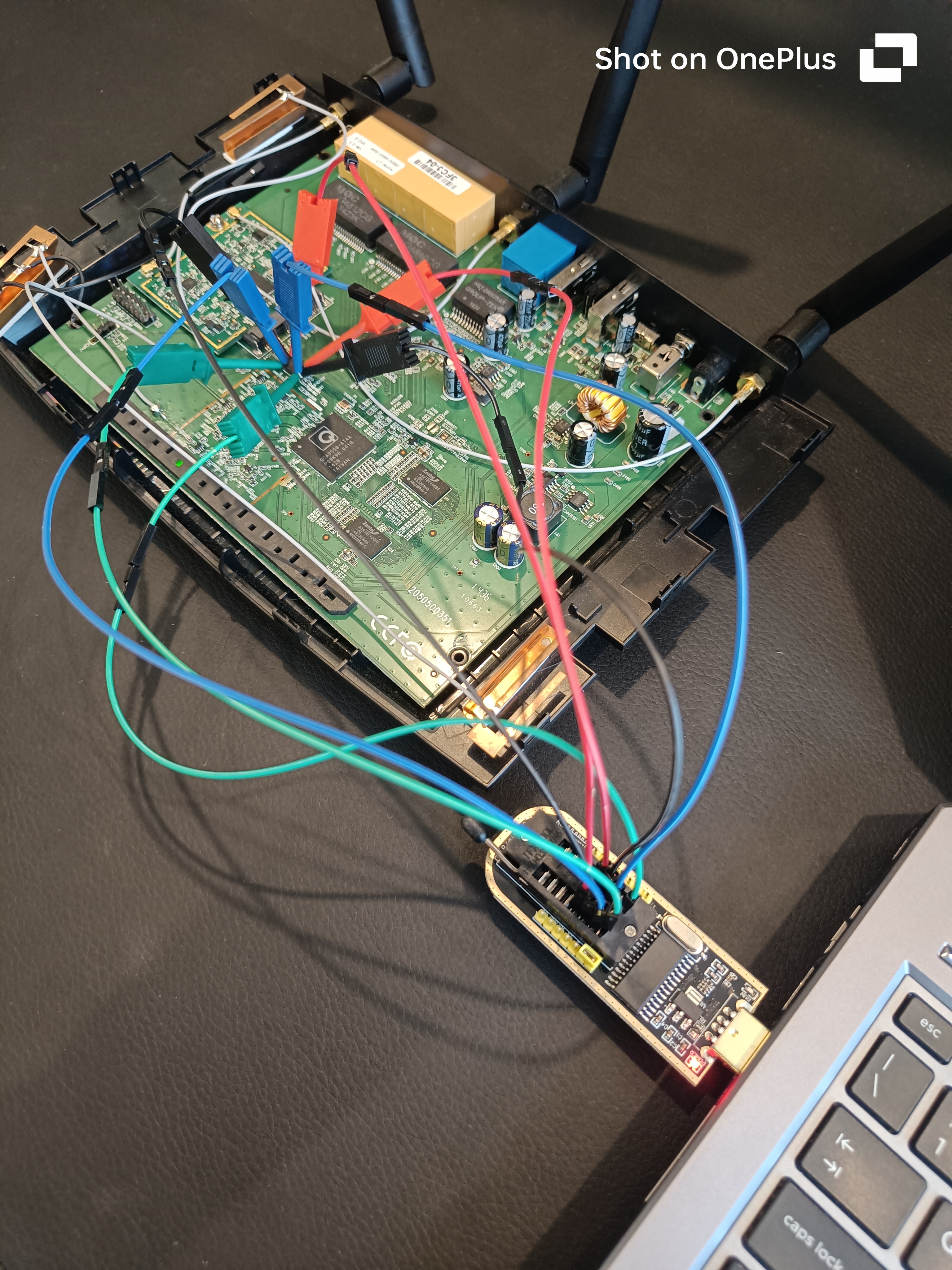
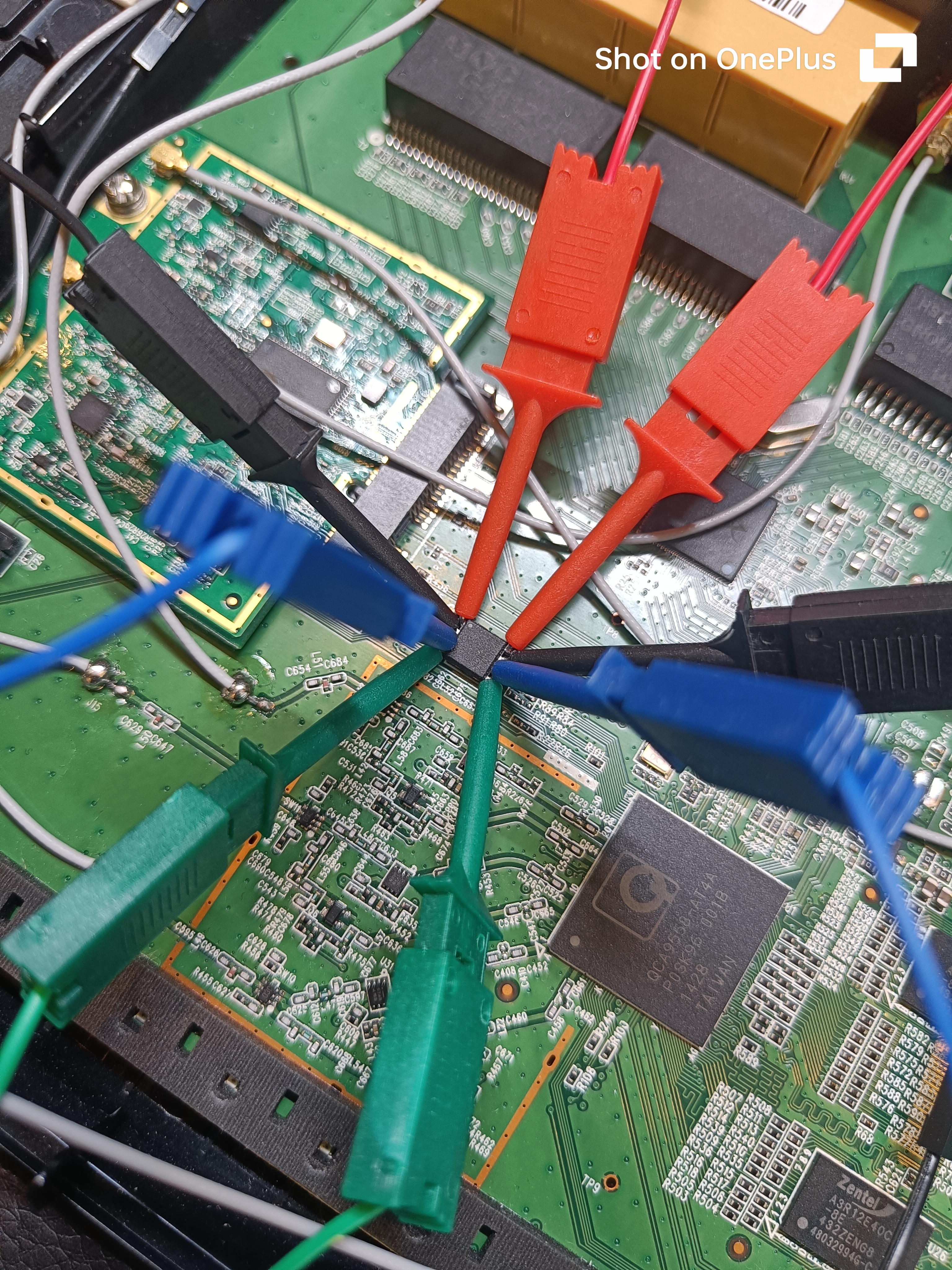
With this setup, the flash chip was recognized and successfully read, as seen in the log below.
┌──(lucas㉿localhost)-[~]
└─$ sudo flashrom -p ch341a_spi -c "S25FL127S-256kB" -r archer_c7_flash.bin
flashrom unknown on Linux 6.8.11-amd64 (x86_64)
flashrom is free software, get the source code at https://flashrom.org

Using clock_gettime for delay loops (clk_id: 1, resolution: 1ns).
Found Spansion flash chip "S25FL127S-256kB" (16384 kB, SPI) on ch341a_spi.
===
This flash part has status UNTESTED for operations: PROBE READ ERASE WRITE WP
The test status of this chip may have been updated in the latest development
version of flashrom. If you are running the latest development version,
please email a report to flashrom@flashrom.org if any of the above operations
work correctly for you with this flash chip. Please include the flashrom log
file for all operations you tested (see the man page for details), and mention
which mainboard or programmer you tested in the subject line.
Thanks for your help!
Reading flash... done.
The extracted firmware was saved to the archer_c7_flash.bin file.
Additionally, a write operation to the firmware was also attempted in order to check if its integrity and availability could be affected. For this, a random byte of the original firmware was changed from the value 0xFF to 0xAA, created a new modified .bin file (archer_c7_modified.bin). Subsequently, the modified firmware was written to flash using the -w flag, as seen in the output below.
┌──(lucas㉿localhost)-[~]
└─$ sudo flashrom -p ch341a_spi -c "S25FL127S-256kB" -w archer_c7_flash_modified.bin
[sudo] password for lucas:
flashrom unknown on Linux 6.8.11-amd64 (x86_64)
flashrom is free software, get the source code at https://flashrom.org

Using clock_gettime for delay loops (clk_id: 1, resolution: 1ns).
Found Spansion flash chip "S25FL127S-256kB" (16384 kB, SPI) on ch341a_spi.
===
This flash part has status UNTESTED for operations: PROBE READ ERASE WRITE WP
The test status of this chip may have been updated in the latest development
version of flashrom. If you are running the latest development version,
please email a report to flashrom@flashrom.org if any of the above operations
work correctly for you with this flash chip. Please include the flashrom log
file for all operations you tested (see the man page for details), and mention
which mainboard or programmer you tested in the subject line.
Thanks for your help!
Reading old flash chip contents... done.
Erasing and writing flash chip... Erase/write done.
Verifying flash... VERIFIED.
As seen, the log confirms the write with the Erase/write done message. The ability to read, write and erase flash contents from the chip has been added as finding MEDIUM-02.
TFTP server and U-Boot
Another common approach to firmware extraction is to copy the flash contents to RAM and then upload the memory contents to a host machine using a TFTP server. For this to work, the tftpput command needs to be available in the U-Boot environment.
Having successfuly interrupted the boot process as detailed in the previous Boot and Runtime Analysis chapter, the existence of this utility was checked via the help command, as seen below.
ap135> help

? - alias for 'help'
bootm - boot application image from memory
cp - memory copy
crc32 - checksum calculation
erase - erase FLASH memory
flinfo - print FLASH memory information
go - start application at address 'addr'
help - print online help
md - memory display
mm - memory modify (auto-incrementing)
mw - memory write (fill)
nm - memory modify (constant address)
printenv - print environment variables
progmac - Set ethernet MAC addresses
protect - enable or disable FLASH write protection
reset - Perform RESET of the CPU
setenv - set environment variables
tftpboot - boot image via network using TFTP protocol
version - print monitor version
While the tftpboot command was present, which allows downloading files from a TFTP server to the device, the corresponding tftpput command (used for uploading memory contents to a remote server) was not, rednering this extraction approach infeasible.
UART flash dump via U-Boot
A final attempt at extraction was performed by dumping the flash contents over the UART interface using the U-Boot command line. This approach was used as a last resort since it is a significantly slower method.
A serial session was opened on the Kali workstation with the command below. The -L flag enabled logging, meaning that all data printed to the terminal was automatically written to a file named screenlog.0.
$ screen -L /dev/ttyUSB0 115200
With the logging serial console enabled, the flash contents were dumped over the UART interface using the following command.
ap135> md.b 0x9f000000 0x1000000
The parameters of this command are:
md.b: U-Boot command to display memory contents in byte format0x9f000000: Starting address containing flash contents (discovered though theprintenvoutput done in the Boot and Runtime Analysis chapter)-
0x1000000: Equivelant to 16MB (which is the size of the flash memory, as detailed in its datasheet and confirmed by summing the partition sizes also reported in the output of theprintenvcommand, as seen below).bootargs=console=ttyS0,115200 root=31:02 rootfstype=jffs2 init=/sbin/init mtdparts=ath-nor0:256k(u-boot),64k(u-boot-env),6336k(rootfs),1408k(uImage),8256k(mib0),64k(ART)
This command caused U-Boot to sequentially print the entire flash memory contents in hexadecimal format over the UART interface. Because the serial terminal logging feature was enabled, the output was automatically captured in a screenlog file on the workstation.
When compared to direct flash extraction, UART flash dump via U-Boot was not only slower but also prone to error. When extracting through this method, the produced screenlog file mentioned above contained missing memory sections. The ability to extract firmware via the UART serial interface and bootloader shell is directly correlated with the previously identified MEDIUM-03 finding.
Firmware Analysis: A preview
Having obtained the firmware through the previously detailed extraction processes, the next step consisted in analysing it. Since the programmer and test clips approach rendered a byte-prefect firmware image (archer_c7_flash.bin), this was the one analysed in the following chapters.
The analysis of the firmware image was conducted in a two stage approach:
Although both these stages cover the same firmware analysis chapter, due to their extensiveness, it was decided to separate them in different files for readability purposes.